Finish-Line Setup
Drivetrain
Tire Setup
Use Measured Tire Rollout
Engine and Shift Settings
Finish-Line Calculation
Closest Common Rear Gear
Finish line RPM: —
Target difference: — RPM
RPM by Gear
Common Ratio Options
RPM After Each Shift
Calculating Quarter-Mile Gear Ratio and Finish RPM
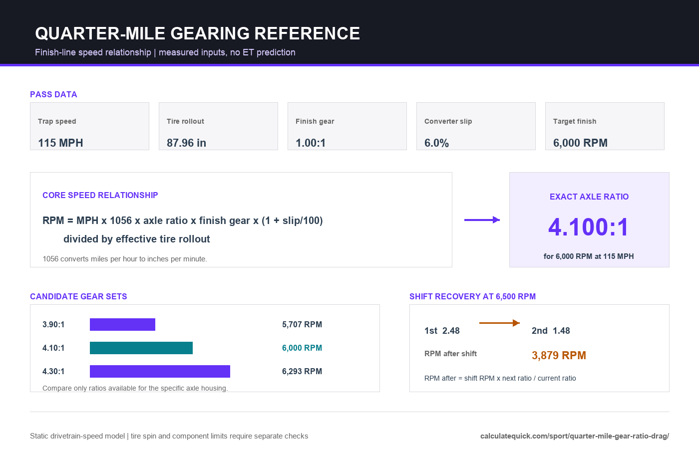
Start with a trap speed from a representative full pass, then enter the engine RPM you want through the finish. The calculator combines that target with effective tire rollout, the transmission ratio actually used through the lights, and converter slip. The exact result is a mathematical axle ratio. The closest available result compares it with the gear sets entered under Exact Setup Options.
Use Check Current Setup when the rear gear is already installed. It calculates finish RPM, speed at redline, and driveshaft RPM at the trap. An optional observed finish RPM also calculates measured converter slip. These are drivetrain-speed relationships, not elapsed-time or traction predictions.
Finish-Line Measurements
| Input | Best source | Check before using |
|---|---|---|
| Trap speed | Timing slip from a clean full pass | Do not use an optimistic horsepower estimate as if it were measured MPH |
| Target finish RPM | Dyno curve, converter behavior and track logs | Keep adequate margin below the engine’s safe limit |
| Transmission ratio | Manufacturer ratio for the gear used through the lights | Do not automatically use the transmission’s highest overdrive gear |
| Tire rollout | Mounted and inflated tire measured around the tread center | Pressure, load, construction and speed can change effective circumference |
| Converter slip | Observed finish RPM compared with locked theoretical RPM | Use zero only for a locked converter or negligible clutch slip |
The 1056 and 336.136 Constants
A vehicle traveling one mile per hour covers 1,056 inches per minute. Dividing that distance by tire rollout gives wheel RPM. Multiplying wheel RPM by axle ratio and transmission ratio gives locked engine RPM. When diameter replaces rollout, circumference is diameter multiplied by pi, so 1,056 divided by pi becomes 336.135… . The conversion follows directly from the exact mile, foot, inch, hour and minute relationships published in the NIST Guide to the SI.
Finish-line engine RPM
RPM = MPH * 1056 * axle ratio * transmission ratio * (1 + slip/100) / tire rollout
Converter Slip at the Finish
Converter slip is the difference between actual engine speed and the locked theoretical engine speed. This calculator expresses that difference as a percentage of locked theoretical RPM, so six percent slip means actual engine RPM is 1.06 times locked theoretical RPM. It is not the converter’s stall speed, flash RPM or launch slip. SAE technical literature describes clutch slip as the speed difference across the torque converter clutch.
To measure finish-line slip, use Check Current Setup and enter an observed engine RPM from the same pass as the trap speed. Verify tire rollout, axle ratio and finish gear first. Tire spin, data-logger error or a guessed tire diameter will appear as converter slip because the formula cannot distinguish among them.
Tire Rollout and Effective Diameter
Mickey Thompson defines rollout as the distance around the mounted and inflated tire and recommends measuring around the center of the tread. Its technical bulletin states that the most accurate diameter calculation is circumference divided by 3.1416. Use rollout mode when that measurement is available.
A sidewall size or catalog diameter is a starting point, not a guaranteed effective diameter through the finish. The manufacturer’s diameter and rollout chart notes that revolutions per mile use approximate loaded radius. This calculator does not add a generic tire-growth allowance because construction, pressure, load and speed are combination-specific.
Transmission Ratio and Shift Recovery
Enter the ratio of the gear the car actually uses through the finish. A direct gear is normally 1.00:1, but overdrive or an intermediate gear may be different. Gear count alone is not enough because transmissions with the same number of speeds can have different internal ratios.
The optional gear stack calculates road speed at the planned shift RPM and the immediate RPM after each shift. Post-shift RPM depends on the ratio step: shift RPM multiplied by next ratio divided by current ratio. It does not identify the best shift RPM because that decision requires the engine’s power curve, acceleration data and shift duration.
Using Candidate Ratios
The exact calculated ratio is rarely a gear set that can be purchased. Edit the available-ratio list to match the ring-and-pinion family used by the car. The comparison chart and table then show finish RPM and maximum-RPM speed for each candidate. A numerically higher ratio raises engine RPM at the same road speed; a numerically lower ratio reduces it.
Treat the nearest candidate as a comparison, not an automatic recommendation. Launch ratio, converter multiplication, tire grip, driveshaft speed, shift recovery and the engine curve can make the second-nearest gear a better package. Record the result with the car’s four-link instant-center and anti-squat setup when evaluating complete launch changes.
Drivetrain and Track Safety
The displayed driveshaft RPM is not a critical-speed rating. Driveshaft material, tube diameter, wall thickness, unsupported length, balance, joint series and operating angle determine the safe limit. Dana’s Driveshaft Application Guidelines explains how tube dimensions, length and operating speed affect critical speed.
Confirm gear-set compatibility, bearing and carrier requirements, pinion depth, backlash, lubrication, fastener torque and driveshaft limits with the component manufacturers or a qualified driveline builder. Recheck containment, wheel and tire ratings, and shutdown-room requirements before increasing finish-line speed or RPM.