Axle-Side X Offsets
Mount geometry
Neutral-line overview
Calculating 4-Link Instant Center and Anti-Squat
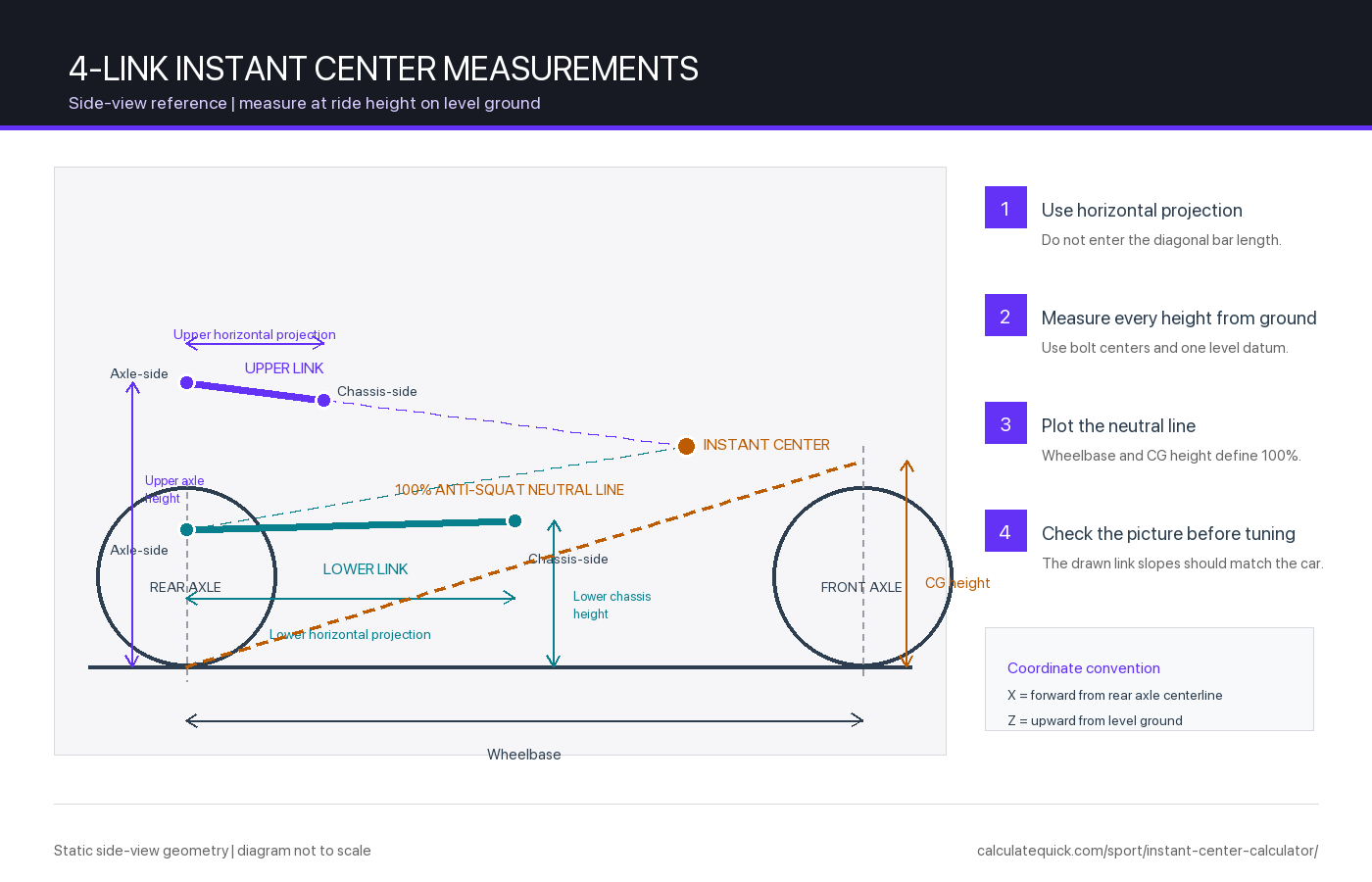
Set the car on level ground at race-ready ride height, then measure from bolt center to bolt center in side view. For each link, enter its horizontal projection and the height of its axle-side and chassis-side bolt centers. The horizontal projection is not the diagonal length of the bar. Add the wheelbase and measured center-of-gravity height to calculate geometric anti-squat.
The result updates as each measurement changes. Instant center length is the forward distance from the rear axle centerline to the intersection of the two projected link lines. Instant center height is measured from the ground. The anti-squat result compares that point with the 100% neutral line. Use the two diagrams to check that the entered links lean in the same directions as the links on the car before relying on the numbers.
Measurement Reference
| Input | Measure between | Common error |
|---|---|---|
| Horizontal projection | Vertical lines through the two bolt centers | Entering the diagonal bar length |
| Axle-side height | Level ground and the axle-bracket bolt center | Measuring from the axle tube or chassis rail |
| Chassis-side height | The same ground plane and the chassis-bracket bolt center | Changing the ground reference between points |
| Wheelbase | Rear and front axle centerlines | Using bodywork or tire-edge dimensions |
| CG height | Ground and the vehicle’s measured center of gravity | Treating crankshaft or camshaft height as an exact value |
Use the axle-bracket offset fields only when an axle-side bolt center sits measurably ahead of or behind the rear axle centerline in side view. Positive X is forward. Most quick plots can leave both offsets at zero. Take every measurement with the driver, fuel and tire pressures in the condition used at the track because a ride-height change alters all four bolt heights.
Instant Center Geometry
The upper and lower links define two straight centerlines in side view. Extending those lines produces their intersection, the instant center. This is the same graphical construction used for a four-bar linkage in the MIT FUNdaMENTALs of Design linkage reference. The calculator solves the intersection from the four measured points without rounding the intermediate coordinates.
A short projected distance between nearly parallel links can move the instant center hundreds of inches with a small height change. That is real geometric sensitivity, not a calculator fault. Exact parallel link centerlines do not have a finite intersection. In that case the calculator reports an instant center at infinity and uses the shared link slope for the limiting anti-squat value. If both centerlines overlap, there is no unique solution and the measurements need checking.
The 100% Anti-Squat Neutral Line
For this solid-axle, rear-wheel-drive side-view model, the 100% line starts at the rear tire contact patch and rises by the ratio of center-of-gravity height to wheelbase. If the instant center lies on that line, the idealized suspension geometry reacts 100% of the acceleration pitch tendency through the links. An instant center above the line gives more than 100% geometric anti-squat; one below gives less than 100%.
Geometric anti-squat
AS% = (IC height / IC length) / (CG height / wheelbase) × 100
Anti-squat is not a traction percentage and does not change the total longitudinal load transfer fixed by vehicle mass, acceleration, wheelbase and CG height. It changes how the suspension reacts to that load through geometric forces instead of spring compression. The University of Southern Queensland’s four-link rear-suspension study covers the same instant-center and anti-squat relationship for drag racing. Real chassis motion also depends on springs, dampers, tire stiffness, unsprung mass, driveline torque, compliance and available grip.
Interpreting Changes to the 4-Link
Work from a measured baseline rather than a universal target. A higher instant center relative to the neutral line increases geometric anti-squat and the tendency for chassis-to-axle separation on the hit. A lower point reduces that geometric reaction and allows more squat through the springs. Moving the instant center closer generally makes the linkage reaction more abrupt, while a longer IC usually spreads the reaction over a longer virtual swing arm. These tendencies do not predict the quickest bracket hole by themselves.
Record the complete setup before moving a bar: all four holes, ride height, shock settings, tire pressure, launch RPM, track condition and 60-foot time. Change one variable, remeasure the geometry, and compare the run. Gearing changes can alter the torque delivered on the hit, so log the quarter-mile gear ratio and tire combination alongside the suspension setting rather than treating anti-squat as an isolated number.
Accuracy Checks Before Changing Bracket Holes
- Confirm the floor is level in both directions and use one ground datum for every height.
- Measure bolt centers, not bracket edges, tube surfaces or rod-end bodies.
- Use horizontal projection for link length. A plumb line or laser makes the two vertical stations easier to mark.
- Plot both sides of the car. If the left and right link coordinates differ, calculate and record each side rather than averaging away a preload or fabrication difference.
- Check the diagram against the actual link slopes. A reversed front/rear height is easier to spot in the picture than in a list of numbers.
- Recalculate after any ride-height, tire-diameter or bracket-hole change because the ground-referenced heights have changed.
Model Limits and Chassis Safety
This calculator is a static side-view geometry tool. It does not solve suspension travel, roll steer, pinion-angle change, driveshaft clearance, lateral location, rod-end articulation, bracket stress, weld strength or fatigue. SAE research comparing theoretical suspension geometry with K&C measurements shows why compliance and tire deflection can separate a real chassis from its rigid-link model. Use the result to document and compare setups, not as proof that a bracket location is structurally safe.
Four-link brackets and bars carry high launch loads. Have a qualified chassis builder review new holes, bracket modifications and welded parts. Confirm rod ends do not bind through travel, maintain adequate fastener edge distance, and inspect the brackets and welds after testing. For a design or fabrication decision with safety consequences, use validated suspension software and physical inspection in addition to this calculation.